The American Flyer Mikado is really a very pretty, well detailed engine. The conversion to DCC is relatively straight forward (I hope!) but I thought it would be worth documenting for anyone else who wants to do it.
Here is some video I shot of the completed locomotive.
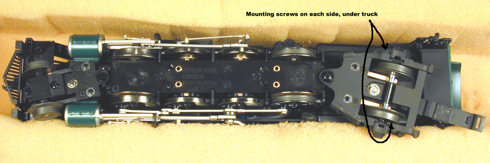
First step is to remove the boiler. There are pickups (thus wires) on both the trailing truck and the pilot truck, so I did not remove them. There are two mounting screws under the cab, and under the trailing truck. Remove them with a small Phillips screwdriver. I used as foam cradle to protect the detail on the loco. By the way, you can click on any photo to see it full size, but they are big, about 200KB.
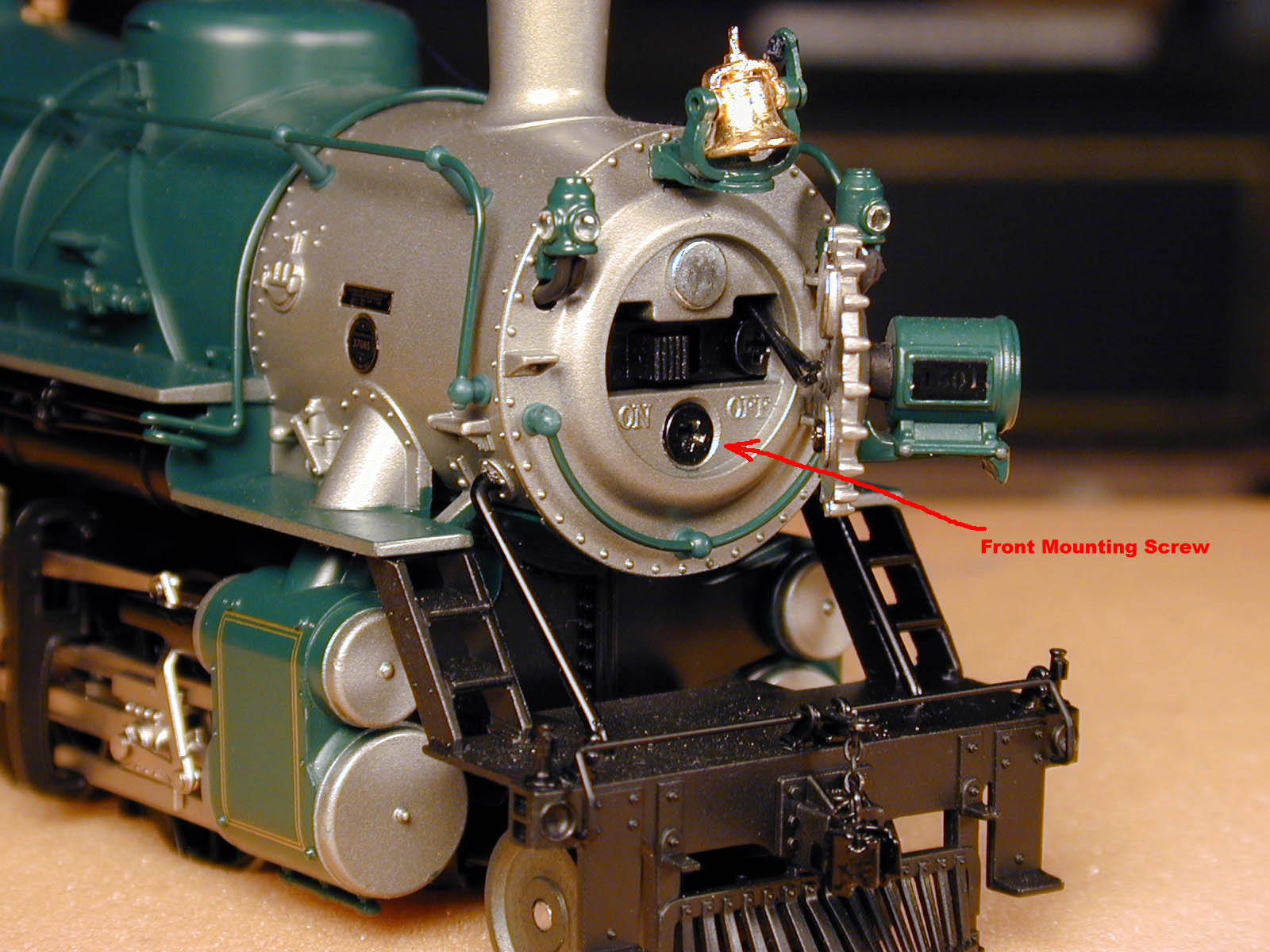
Remove the front mounting screw under the smoke box cover. The cover is hinged, and held closed with a small magnet. Neat! At this point, the boiler can be lifted off the chassis. There will be several wires between the boiler and chassis, however, so you have to keep them close. The wire guards from the pilot deck to the boiler will unplug from the boiler as you lift it off.
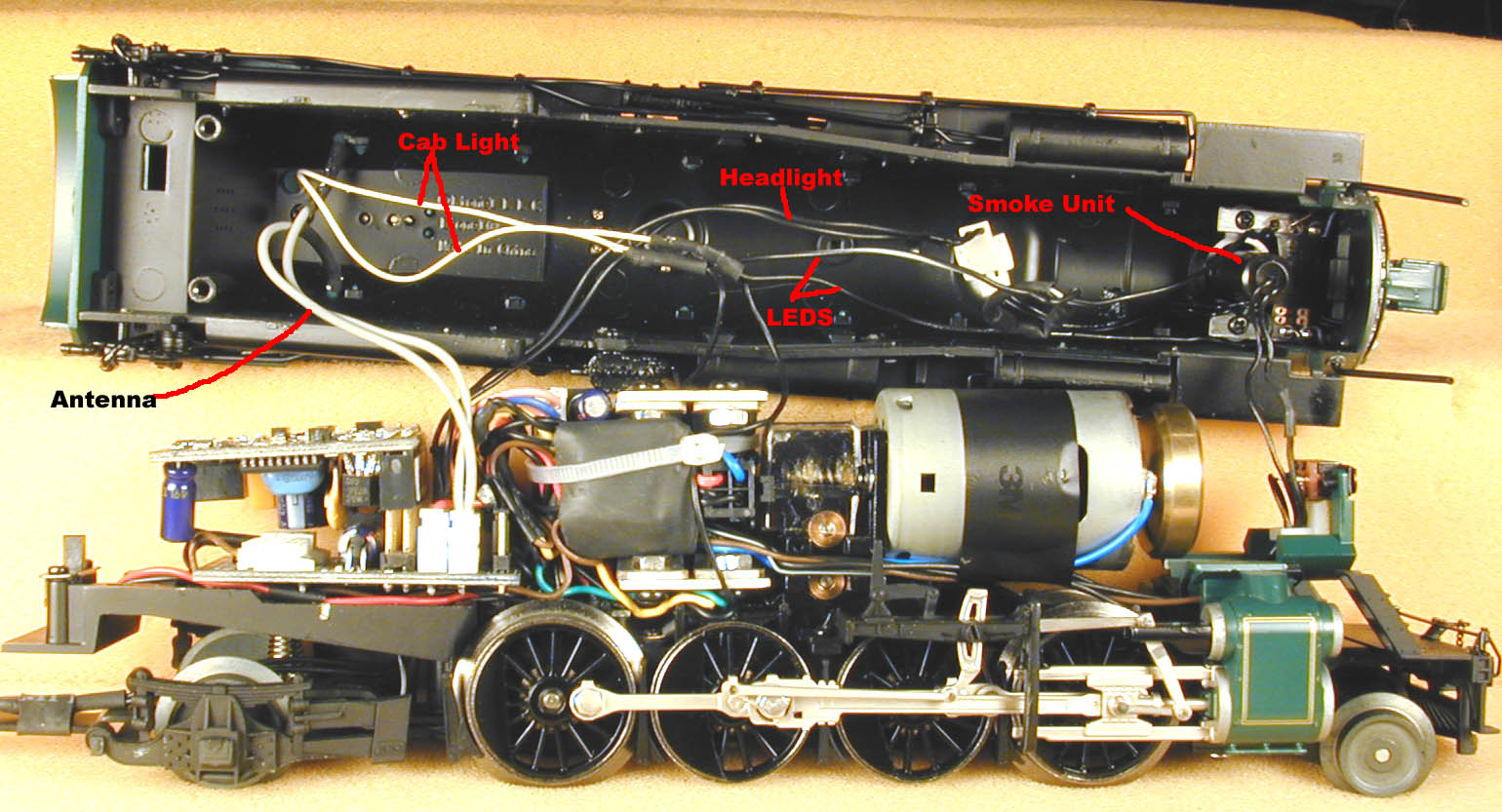
Here is the unit with the boiler removed. The large block of electronics is the TMCC system, which we will be removing. I've labeled the wires in the boiler.
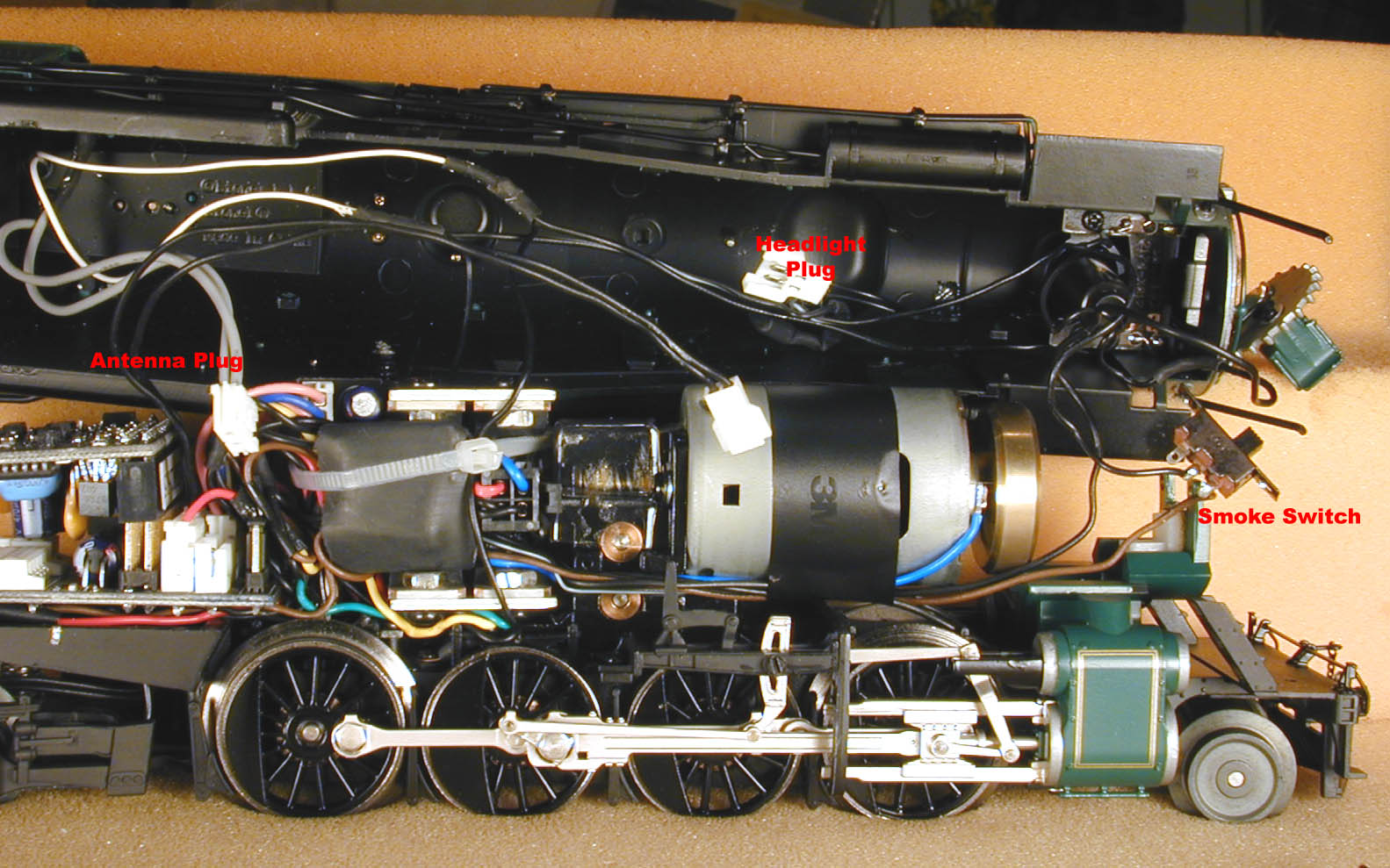
I removed the small screws holding the smoke switch so that I could get at the wires. Unplug the antenna and headlight plugs, cut the black wire from the smoke unit to the chassis, and unsolder the brown wire from the switch. Now the boiler and chassis are completely separate.

Unplug and remove the top PCB (printed circuit board). The two mounting screws that hold the bottom PCB in are now accessible. You can't really see the front one in the picture, its hidden beneath the wires. But its easy to reach with your small phillips screwdriver. Remove the screws and carefully pull the board away a little so you can see what's under it.

The large Alluminum mount is secured with one screw, shown here. Remove the screw, and ease the aluminum mount with all its electronics up.
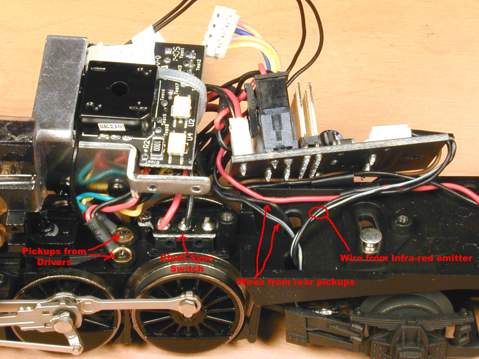
Next, remove the screws holding the teminals for the driver pickup wires. Unplug the wires from the infra-red emitter (plug on board). Unsolder the two wires from the chuff sync switch. Cut the two wires from the trailing truck pickups, and the two from the pilot truck pickups.
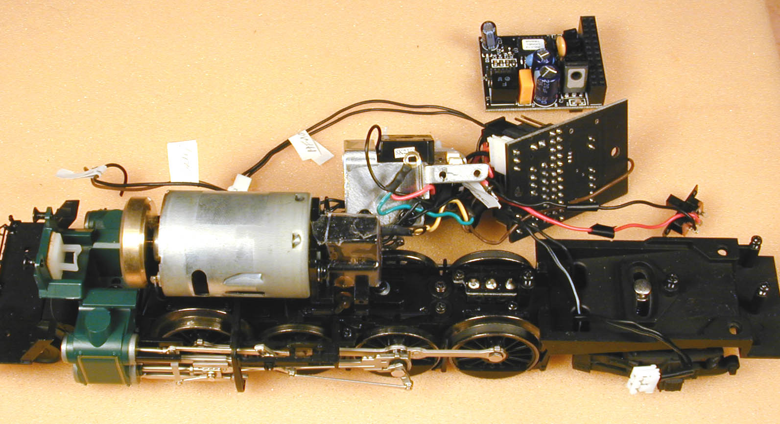
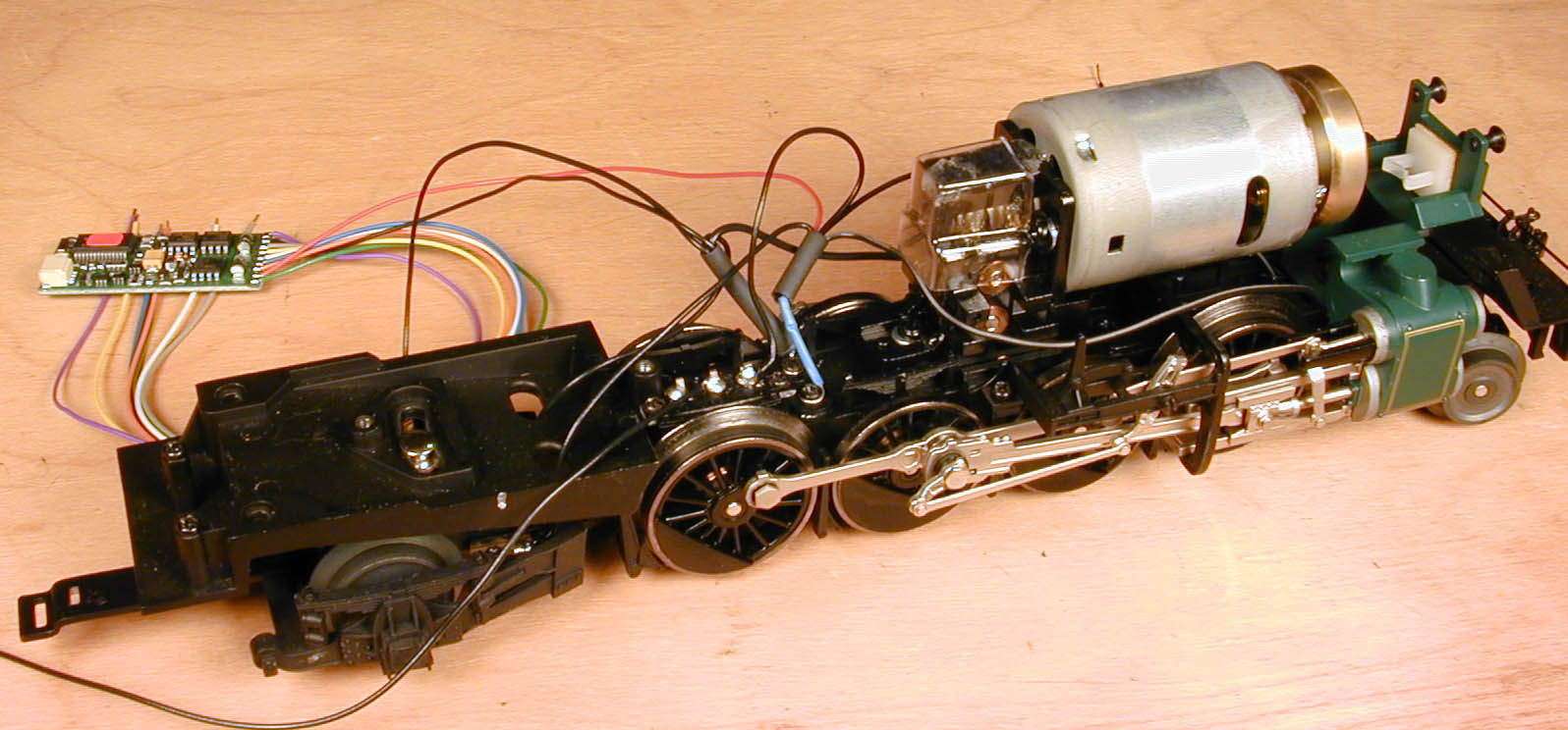
Here is the loco with the TMCC system removed.
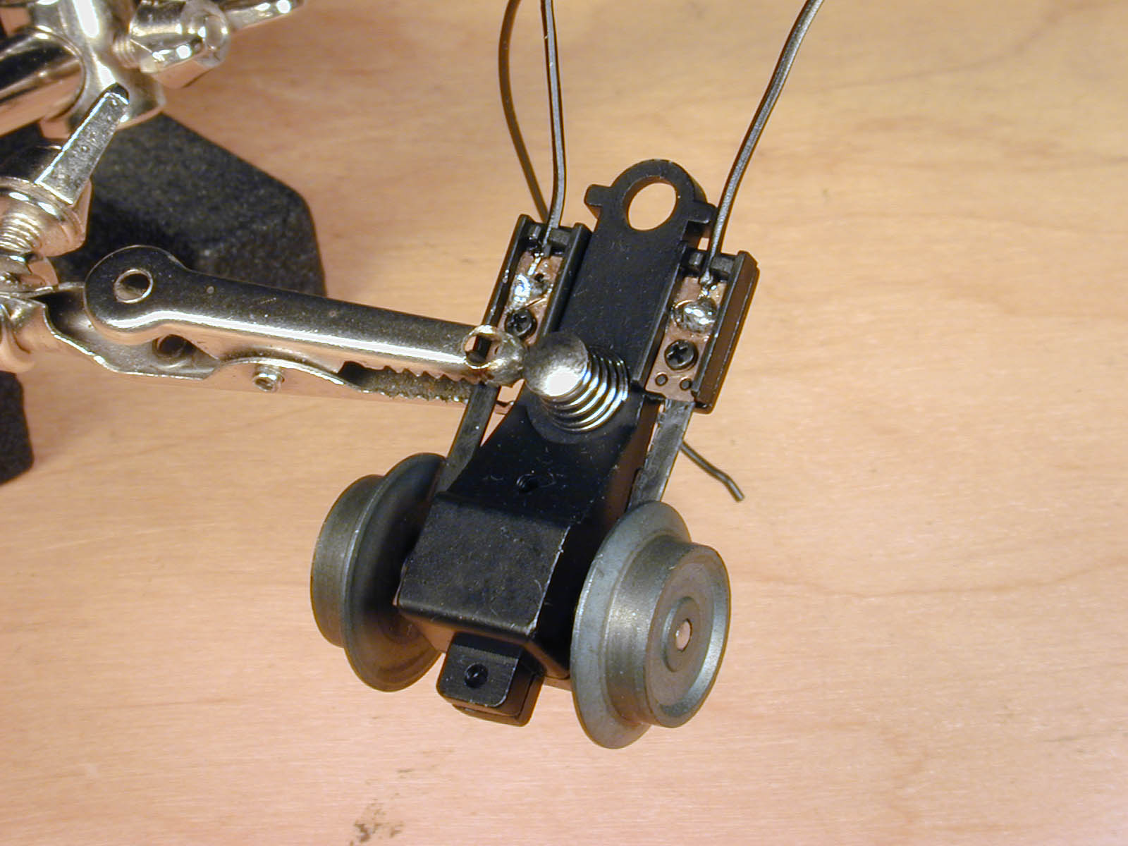
The wires coming from the pickups on the pilot truck are too short, so instead of splicing extensions I decided to replace them. One screw removes the truck, and it is easy to solder 6" wires to replace the originals.
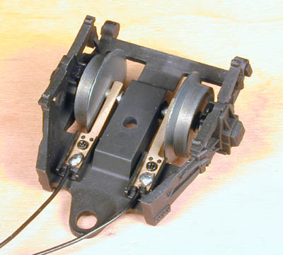
Same with the trailing truck. This required removing one screw and a C clip. I replaced with 5" wires.

The screws where the blue wires are attached are the connection to the driver pickups. On the left side, I connected the front and rear trucks, the black wire from the Lenz Gold decoder, and an extra wire to go to the smoke relay. The right side has the front and rear trucks, a wire to the chuff sync switch, and a wire to go forward to the smoke unit on/off switch. I also soldered an 8" wire to the center pin of the chuff sensow switch. This wire will go to the Tsunami in the tender, and be used for chuff synchronization.
Here's a view of the loco so far.
I decided to build a board to mount the resistors, relay, and decoder on. This isn't really necessary, but it keeps everything a little neater. I cut my board out of PCB material, you could also use plastic or even balsa wood. Dimensions of the board are 2" x 1.1". I decided to use mounting posts already available in the loco, so I drilled one hole .25" from one end, in the center, and the other 1.52" away, using a #39 bit.
Install the relay onto the board. I made a ohm 6 watt resistor by putting 3 39 ohm 2 watt in parallel. Connect the left side extra wire from the step above to one end of the relay. Connect one end of the resistor to the other end of the relay. Connect a 5" wire to the other end of the resistor, to be connected to the smoke unit.
Connect the orange wire from the Gold-JST decoder to to the right side motor terminal. Connect the grey wire to the left side motor terminal.
Connect the blue wire from the Gold-JSt to one side of the relaay coil. Connect a blue extension wire to it to go to the lights in the boiler. Connect the yellow wire to the other side of the coil.
The headlight and cab light are bulbs, so polarity doesn't mater. The markers are LEDs, so polarity is important. Positive is the lead with the components in the lead (under shrinkwrap). Connect the positive lead from the marker ligts, one lead from the cab light, one lead from the headlight, and the blue extension wire from the board. Connect the green wire from the Gold-JST to the other wire from the cab light, the violet wire to the other side of the marker lights, and the white wire to the other side of the headlight. Cove all connections with shrinkwrap.
Part 2 will cover adding sound to the tender.