American Models new 4-8-4 Northern is an ideal subject for installing DCC. The fact there is so much room in the boiler offers some options for just how the installation can be done. After studying the situation and layout, I decided to use 2 decoders, a Lenz Gold-JST for motor, smoke, and lights, and a SoundTraxx Tsunami for sound. The Tsunami might work for everything, but the motor draws more current at stall than I was comfortable with.
The basic layout for this installation is to rewire the loco so that the 2 outer wires on the 4 pin plug are the motor, and the 2 inner pins are the headlight and smoke unit. The decoders go in the tender with the speaker. I use a small reed relay for the smoke and headlight.
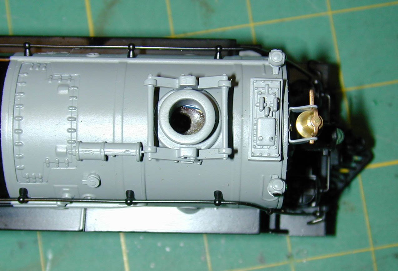
Start by removing the chassis from the boiler. I always unscrew the smoke stack pipe to avoid damaging it.It is already removed in this picture.
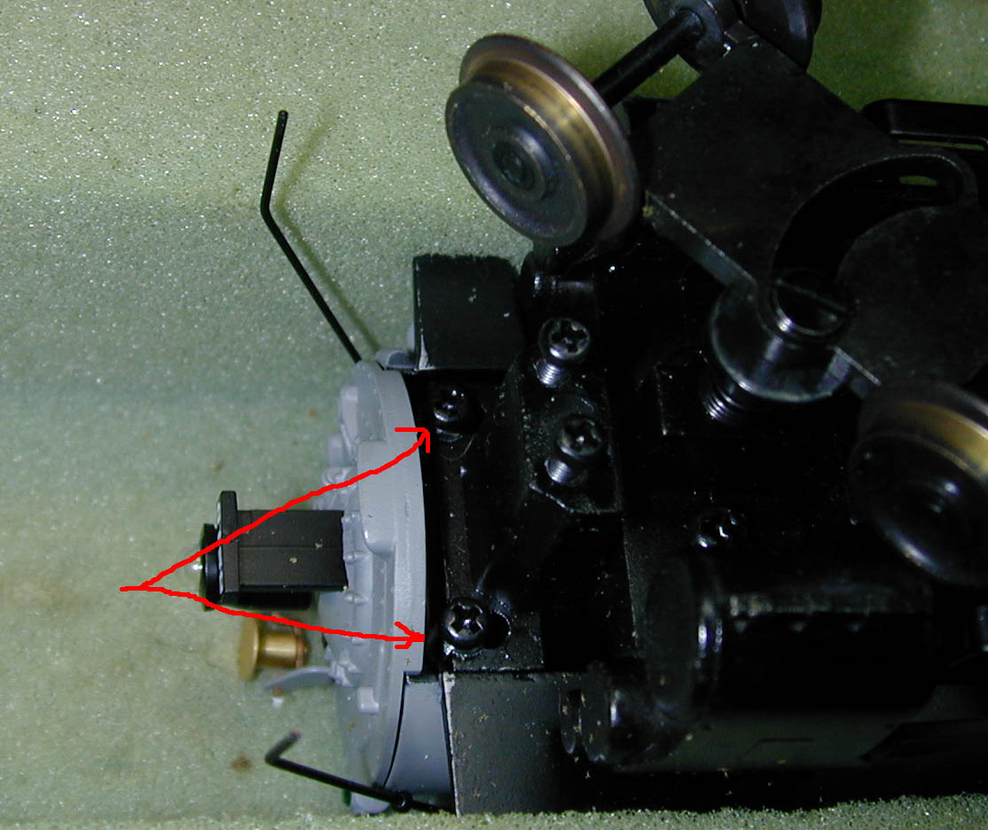
Next, the smoke switch in the cab needs to be detached to allow the boiler to come off. Remove the 2 small screws at the bottom.
You need to remove the pilot to get at the fromt mounting screws. Remove the 2 small screws and carefully lift the pilot off the gaurd wires.
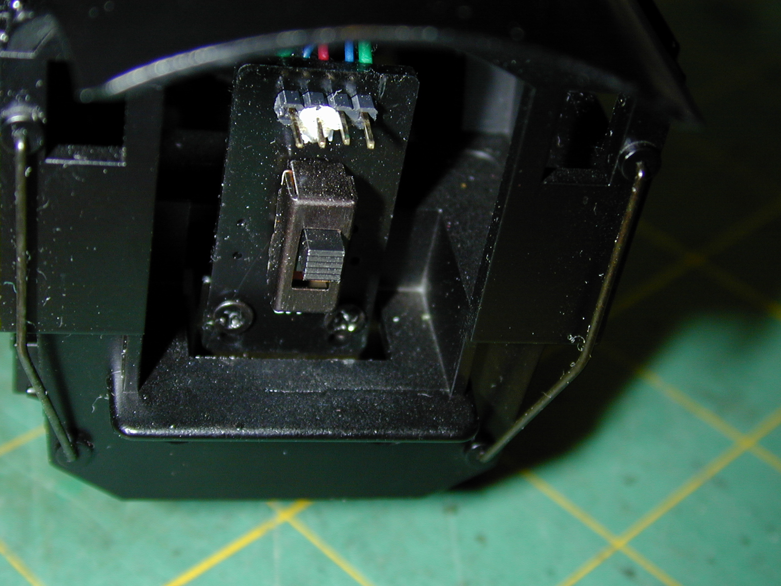
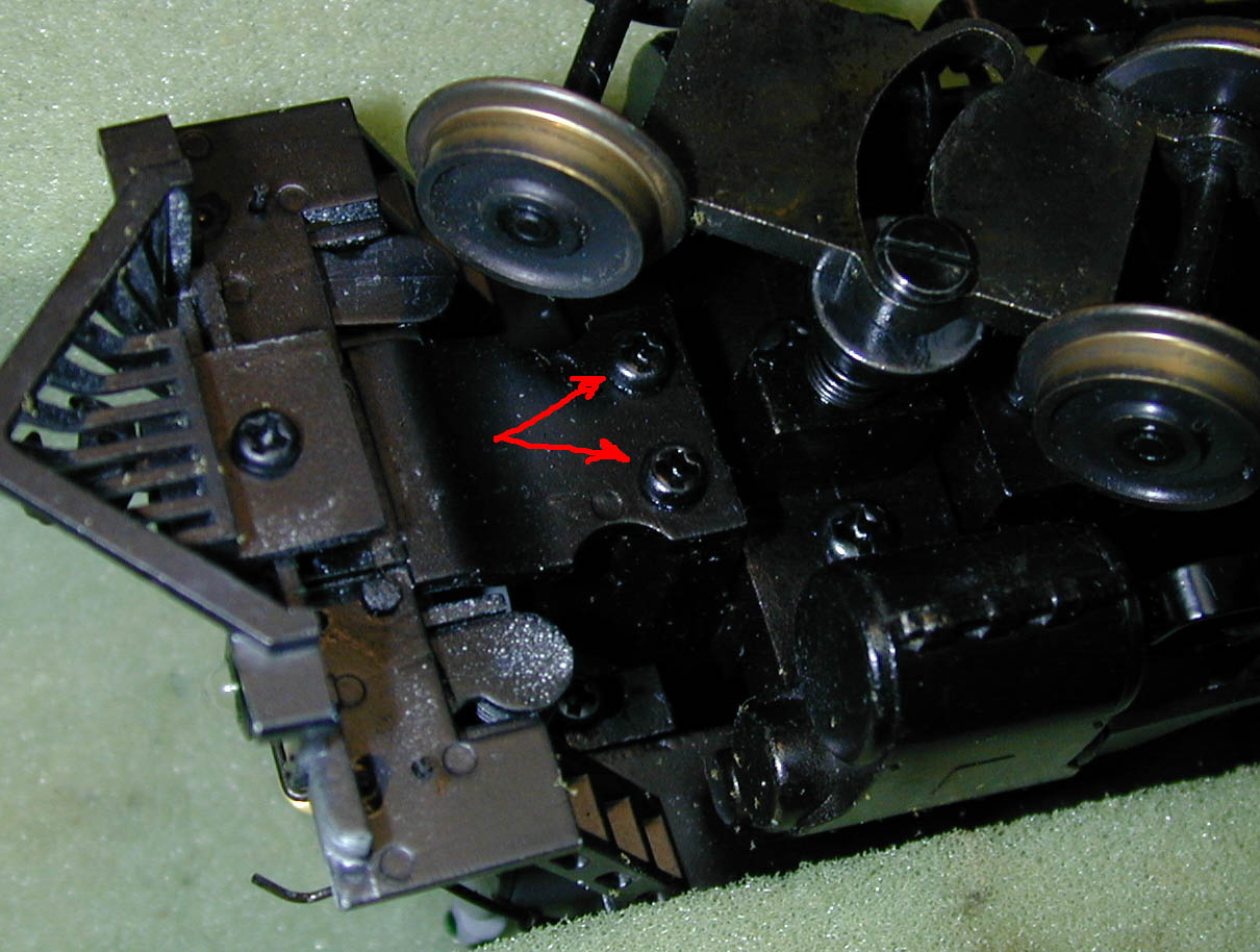
Now you can remove the two front mounting screws.
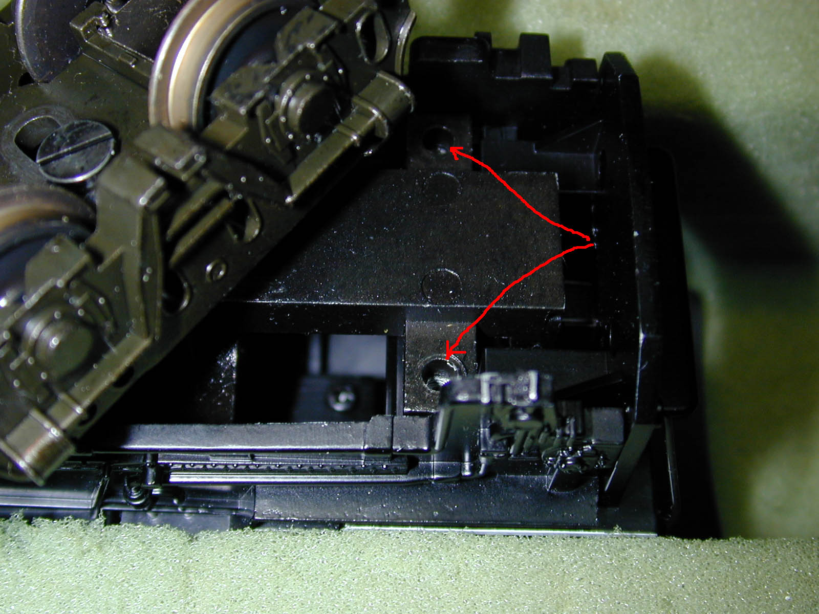
Finally, remove the 2 rear mounting screws under the cab. The chassis will lift straight out. Be careful not to stretch the headlight wires. There is a plug in the headlight wire secured with clear tape. Remove the tape and unplug the headlight. Put the boiler aside.
The 2 rear mounting screws are the largest. The front mounting screws are the same tread as the screws that hold the pilot, but longer.
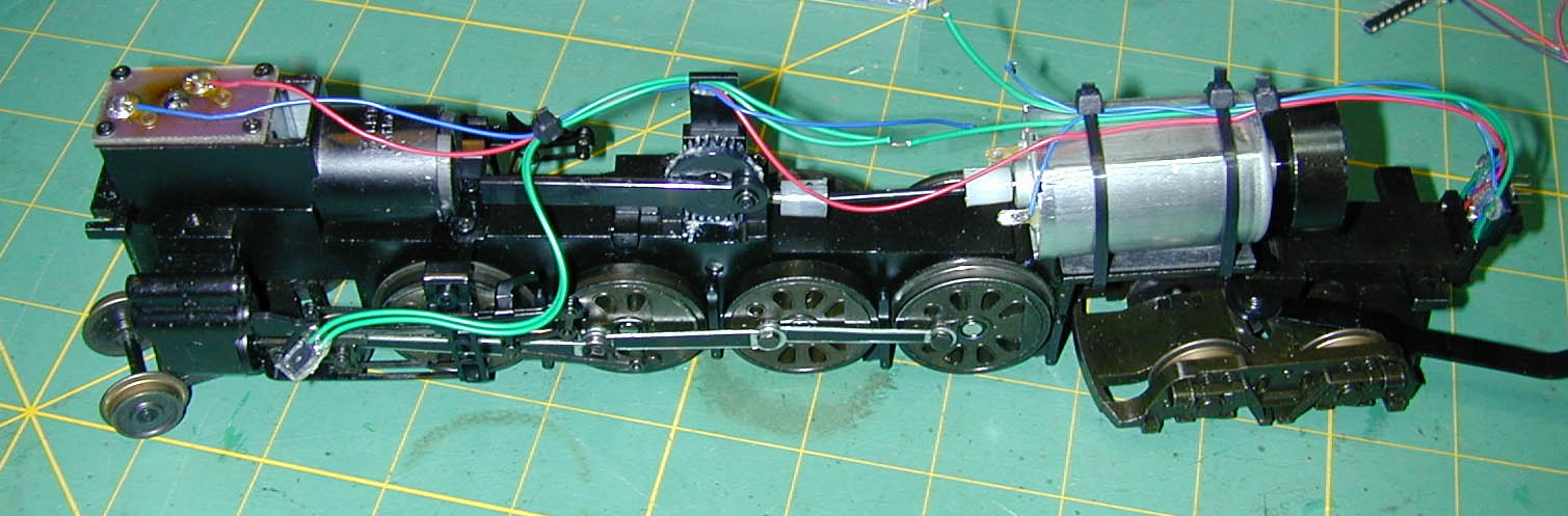
Here's the chassis. The 2 blue wires that go to the motor terminals need to be desoldered. Cut the 2 green wires going to the headlight such that they will reach the motor terminals. I number the pins on the smoke switch/plug 1-4, left to right, looking from the rear of the loco. The green wire from pin 1 goes to the right side terminal, the green wire from pin 4 to the left terminal.
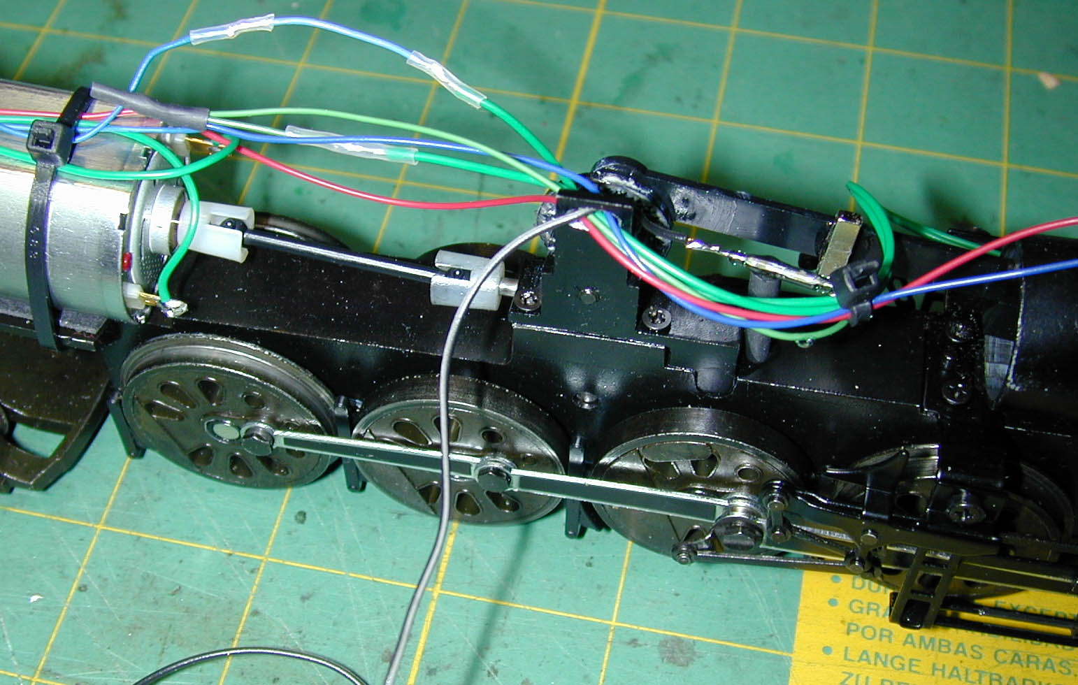
The blue wire from pin 3 connects to the blue wire from the smoke unit, either green wire from the headlight, and about a 5" piece of wire which will be used for the smoke sync switch. The blue wire from pin 2 connects to the other green wire from the headlight.
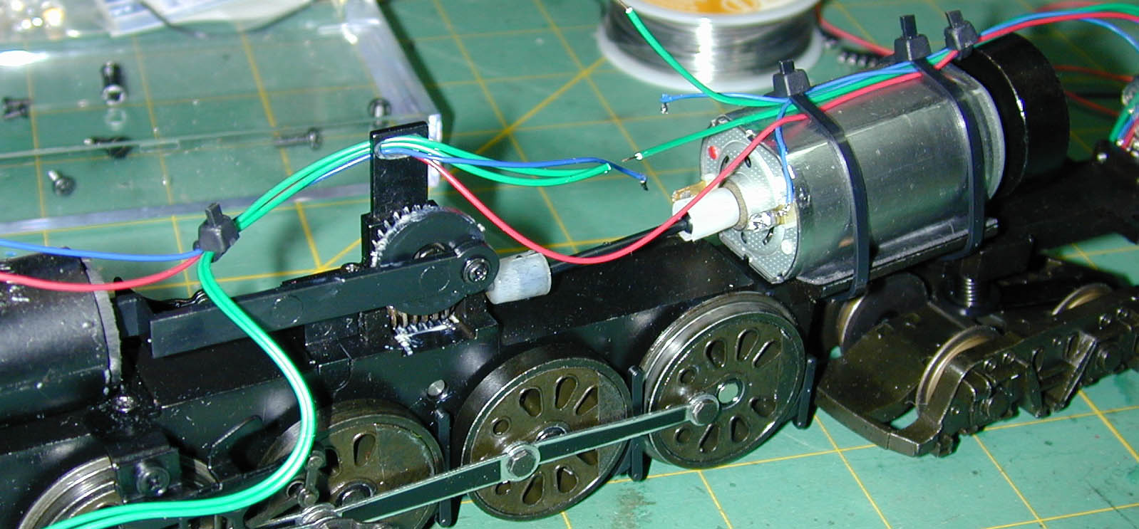
Add a lever or magnetic switch for the chuff sync. In this case I used a Mimiatronics magnetic switch. The magnet is epoxied to the connecting rod of the smoke piston. The reed switch is epoxied to a mount made out of some shrink wrap. Each time the piston pushed smoke out the reed switch will open, causing a chuff from the Tsunami.
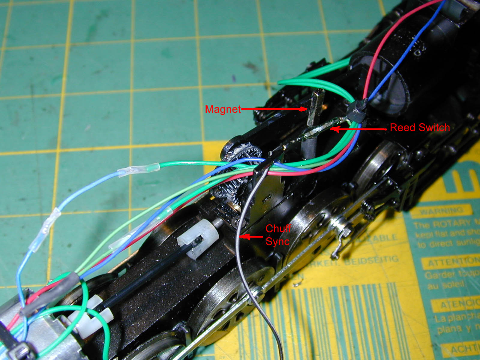
Here's another view of the switch and magnet. One side is connected to the extra wire you connected to the blue wire from pin 3. The other side of the switch is a wire which will be connected to the Tsunami sync wire from the tender.
This completes the rewiring of the chassis. Leave the boiler off until its tested.
Here's the programming I used:
| Short Address | 3 |
| Long Address | 2923 (Locomotive Road Number) |
| CV 3 | 40 |
| CV 4 | 30 |
| CV 39 | 128 F5 Dim Headlight |
| CV 40 | 2 F6 Smoke On/Off |
| CV 41 | 128 F7 brake squeal |
| CV 61 | 10 Brake Rate |
| CV 112 | 128 Cam sync |
| CV 128 | 128 Master Volume |
| CV 198 | 18 Auto sound |
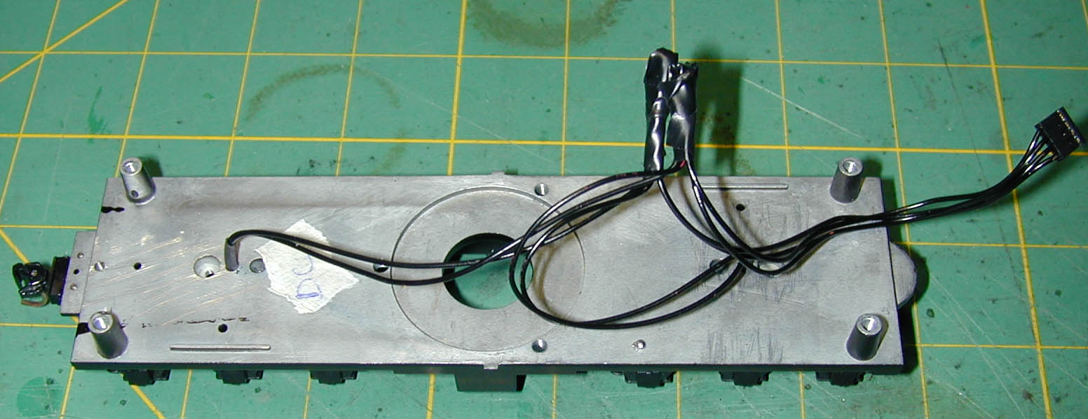
The shell comes off the tender by carefully spreading it shightly in the middle, which allows it to come off the tabs in the middle of each side of its chassis. Here's the tender chassis. The wires are from the pickups.Remove the electrical tape and desolder the plug.
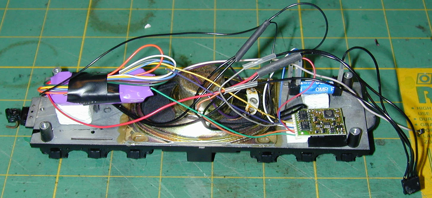
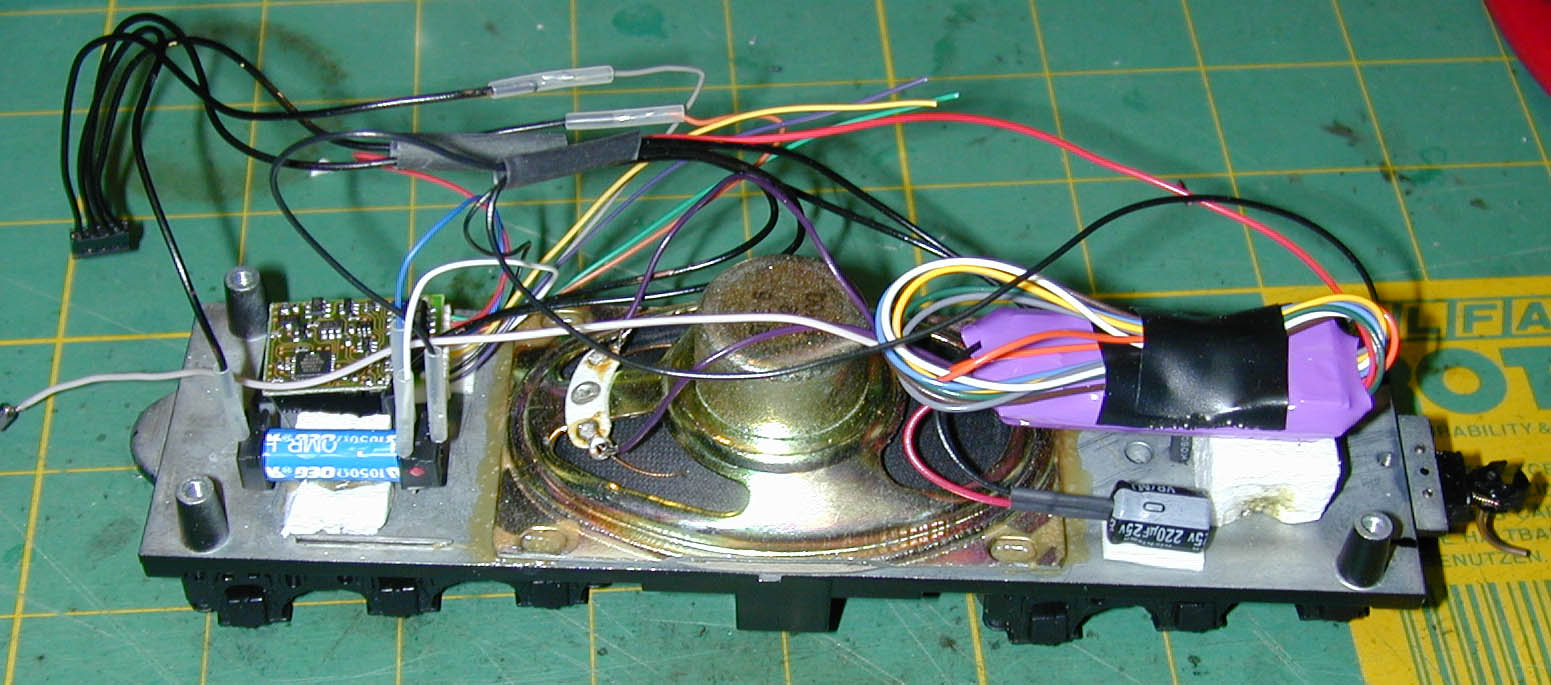
I mounted the various devices before any wiring. I used a Miniatronics large oval speaker. This was actually a bit too wide to fit in the tender, so I gound a little off each side to make it fit. I then glued it in place using goop. The Lenz decoder was mounted using double-sided foam tape contacting only the plug. I put a piece of electrical tape on the tender floor under the decoder to prevent a short if the decoder should come loose or get pushed down. The Tsunami had to go over the speaker a little to fit, so I mounted it on a small block of foam using goop. I also used a foam block for the relay.
The red wires from each of the decoders and pin 3 from the plug are connected to the right side pickups. The black wires from the decoders and a wire to the switched contacts on the relay are connected to the left side pickups. The other switched contact from the relay connects to pin 2 of the plug. Blue and white from the Lenz connect to the coil of the relay. Thus, when F0 is on, the relay is energised and power goes to the headlight and through the smoke switch to the smoke unit. I wire the headlight in parallel with the smoke unit so it is an indication of when the smoke unit is on. Grey from the Lenz goes to pin 1 of the plug, orange to pin 4. The speaker wires from the Tsunami attach to the speaker. I use a small plug made from a pc header for the sync wire.
Connect the 4 pin plug and the chuff sync plug and put the loco/tender on the track and test. Once you are sure everything works, put the shell on the tender and boiler on the loco and you are done!